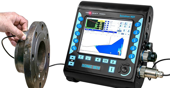
Phased array ultrasonic (PA) is an advanced method of ultrasonic testing that has applications in medical imaging and industrial non-destructive testing. Common applications are to noninvasively examine to find flaw in materials such as welds. To test or interrogate a large volume of material, a conventional probe must be physically scanned (moved or turned) to sweep the beam through the area of interest. The scanned data will display the A- scan , B-scan , C- scan & S- Scan screen representations which helps to analyse the defect in different views. In contrast, the beam from a phased array probe can be focused and swept electronically without moving the probe. The beam is controllable because a phased array probe is made up of multiple small elements, each of which can be pulsed individually at a computer-calculated timing. The term phased refers to the timing, and the term array refers to the multiple elements.
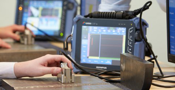
Phased array is widely used for non-destructive testing (NDT) in several industrial sectors, such as construction, pipelines, and power generation. This method is an advanced NDT method that is used to detect discontinuities i.e., cracks or flaws and thereby determine component quality. Due to the possibility to control parameters such as beam angle and focal distance; this method is very efficient regarding the defect detection and speed of testing. Apart from detecting flaws in components, phased array can also be used for wall thickness measurements in conjunction with corrosion testing.
(Plate & Pipe Samples):

Finding Sub- Surface Indications on Carbon Steel Butt Weld Plates
Finding Sub- Surface Indications on Carbon Steel Butt Weld Plates
Finding Sub- Surface Indications on Carbon Steel Butt Weld Pipes
Finding Sub- Surface Indications on Carbon Steel Butt Weld Pipes
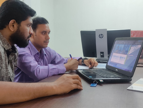
Interpretation of PAUT data on analysis software (OMNIPC/TOMOVIEW)
Interpretation of PAUT data on analysis software (OMNIPC/TOMOVIEW)
Measuring the amplitude of reflected signal is a relatively unreliable method of sizing defects because the amplitude strongly depends on the orientation of the crack. Instead of amplitude, TOFD uses the time of flight of an ultrasonic pulse to determine the position and size of a reflector. In a TOFD system, a pair of ultrasonic probes sits on opposite sides of a weld. One of the probes, the transmitter, emits an ultrasonic pulse that is picked up by the probe on the other side, the receiver. In undamaged pipes, the signals picked up by the receiver probe are from two waves: one that travels along the surface and one that reflects off the far wall. When a crack is present, there is a diffraction of the ultrasonic wave from the tip(s) of the crack. Using the measured time of flight of the pulse, the depth of a crack tips can be calculated automatically by simple trigonometry.
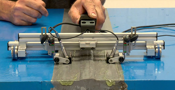
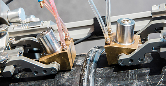
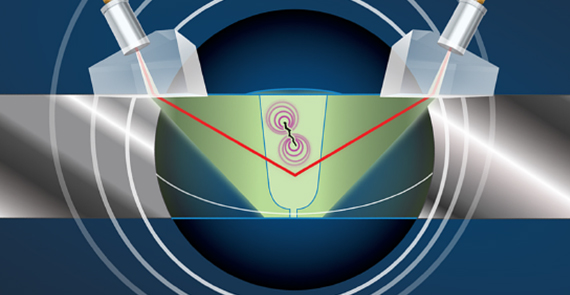
Phased Array + TOFD combination is commonly used to inspect pipeline welds. One of the limitations of TOFD is the "dead zone' created by the lateral wave signal just below the inspection surface (or OD surface in case of the pipe). The dead zone is approximately 5 mm and there is no flaw detection in this zone. Calibration blocks with side drilled holes as used to validate the "dead zone" and sizing accuracy.
(Plate & Pipe Samples):
Finding Sub- Surface Indications on Carbon Steel Butt Weld Plates
Finding Sub- Surface Indications on Carbon Steel Butt Weld Plates
Finding Sub- Surface Indications on Carbon Steel Butt Weld Pipes
Finding Sub- Surface Indications on Carbon Steel Butt Weld Pipes
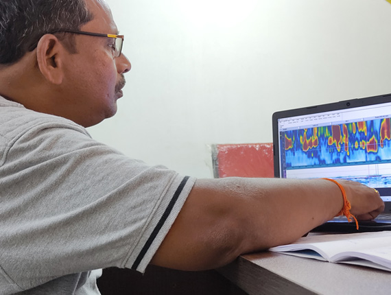
Interpretation of TOFD data on analysis software (OMNIPC/TOMOVIEW)
Interpretation of TOFD data on analysis software (OMNIPC/TOMOVIEW)
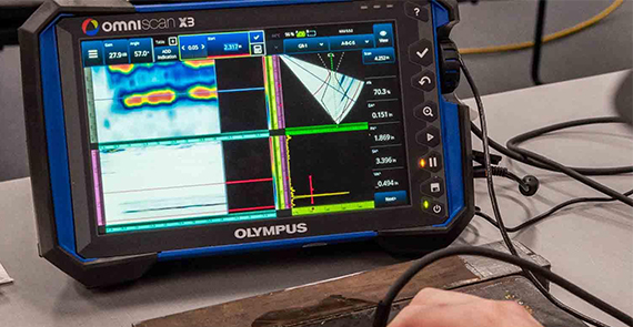
PAUT/TOFD Data Interpretation and evaluation shall be done in the software after the data acquisition shows in colour pallet. The data represents in different views such as A- Scan, B-Scan, C-Scan, S-Scan… This Screen representation plays an important role in finding the defect Datum, Length, Height, location on the weld, maximum amplitude by adjusting the angles.
GK NDT designed this training program for the Inspectors to acquire the knowledge in advanced technologies through PAUT/TOFD data analysis, evaluation or review in the software. The evaluation shall be in different applicable codes which helps to understand and correlate in the industries