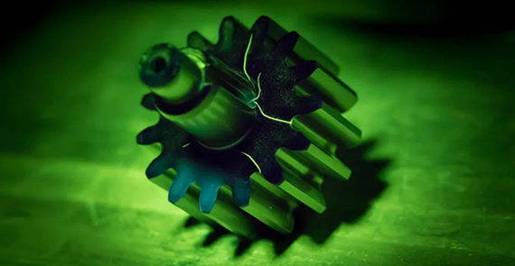
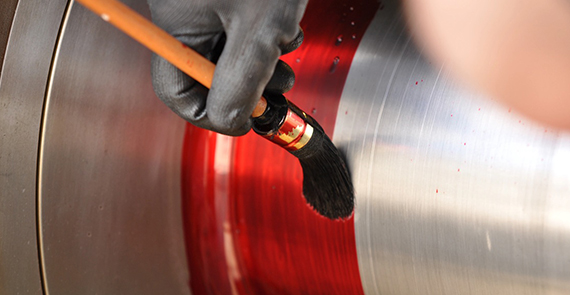
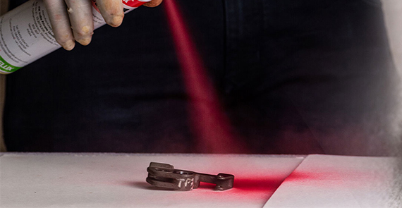
The principle of liquid penetrant testing is that the liquid penetrant is drawn into the surface-breaking crack by capillary action and excess surface penetrant is then removed; a developer (typically a dry powder) is then applied to the surface, to draw out the penetrant in the crack and produce a surface indication.
(Fluorescent/Non-Fluorescent Dry &Wet Medium):

Finding Surface Indications on Carbon Steel Butt Weld Plates

Finding Surface Indications on Carbon Steel Butt Weld Plates

Finding Surface Indications on Carbon Steel Butt Weld Pipes

Finding Surface Indications on Carbon Steel Butt Weld Pipes

Finding Surface Indications on Carbon Steel Butt Weld T-Joints

Finding Surface Indications on Carbon Steel Butt Weld T-Joints
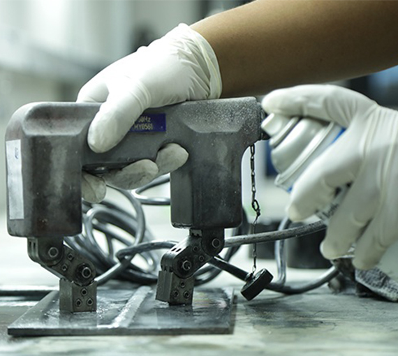
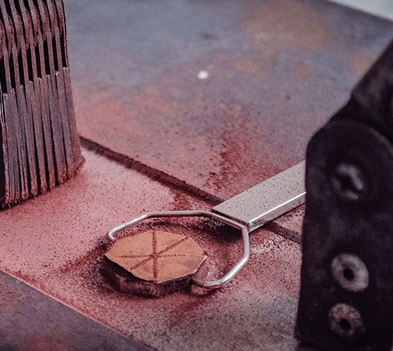
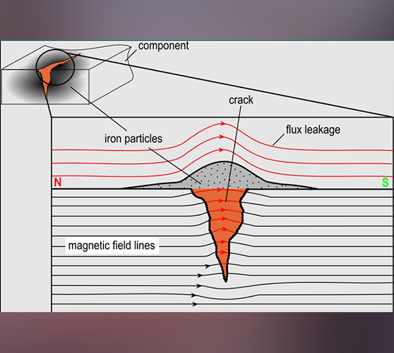
This method is used for the detection of surface and near-surface flaws in ferromagnetic materials and is primarily used for crack detection. The specimen is magnetised either locally or overall, and if the material is sound the magnetic flux is predominantly inside the material. If, however, there is any surface-breaking flaw, the magnetic field is distorted, causing local magnetic flux leakage around the flaw. This leakage flux is displayed by covering the surface with very fine iron particles applied either dry or suspended in a liquid. The particles accumulate at the regions of flux leakage, producing a build-up which can be seen visually even when the crack opening is very narrow. Thus, a crack is indicated as a line of iron powder particles on the surface.
The method is applicable to all metals which can be strongly magnetised - ferritic steels and iron, but not generally austenitic Stainless steels.
(Fluorescent/Non-Fluorescent Dry &Wet Medium):

Finding Surface Indications on Carbon Steel Butt Weld Plates

Finding Surface Indications on Carbon Steel Butt Weld Plates

Finding Surface Indications on Carbon Steel Butt Weld Pipes

Finding Surface Indications on Carbon Steel Butt Weld Pipes

Finding Surface Indications on Carbon Steel Butt Weld T-Joints

Finding Surface Indications on Carbon Steel Butt Weld T-Joints
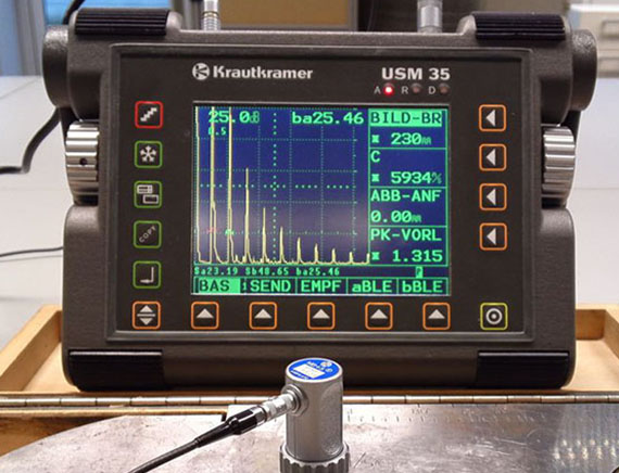
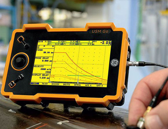
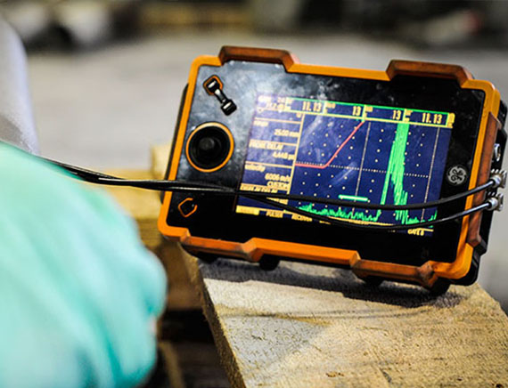
When the acoustic impedance mismatch at interface means there will be change in the density and velocity of the two adjacent materials. Further some part of the sound will be reflected at joining of two materials (Interface) and some part of the sound will be transmitted into the second medium. Thus, the reflected energy will be received by the probe and will display a Signal in the CRT Monitor.
In UT a sound pulse is sent into a solid object and an echo returns from any flaws in that object or from the other side of the object (See below figure). An echo is returned from a solid-air interface or any solid-non-solid interface in the object being examined.

Finding Surface Indications on Carbon Steel Butt Weld Plates

Finding Surface Indications on Carbon Steel Butt Weld Plates

Finding Surface Indications on Carbon Steel Butt Weld Pipes

Finding Surface Indications on Carbon Steel Butt Weld Pipes

Finding Laminations in Base Metal
and All Calibration Methods

Finding Laminations in Base Metal
and All Calibration Methods
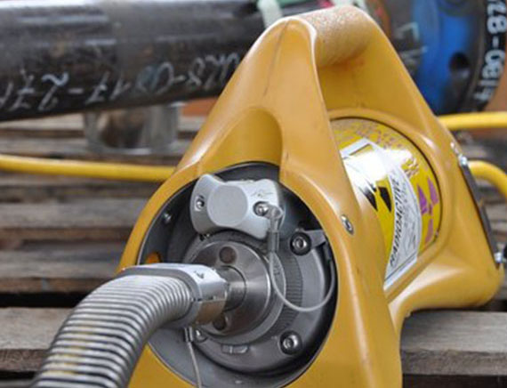
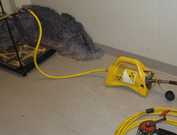
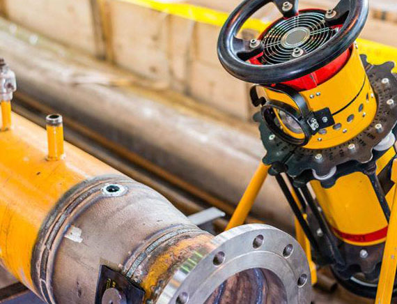
Radiographic testing (RT) is a powerful volumetric inspection method, which employs ionizing radiation as its probing medium. Although there are many safety considerations for the use of ionizing radiation, an advantage of RT over other methods is that many RT techniques provide a permanent record of test results. Specimens may be individual components or assemblies, virtually any material type may be tested, and the range of sample size is considerable. Most RT techniques have the radiation source and radiation detector (Film) on opposite sides of the test object. The localized attenuation of penetrating radiation indicates changes in cross-sectional thickness and/or density on the film shows either black or white indications.
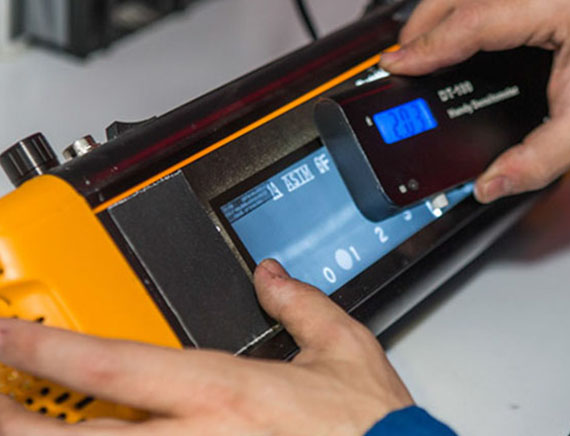
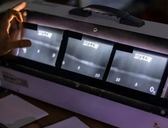
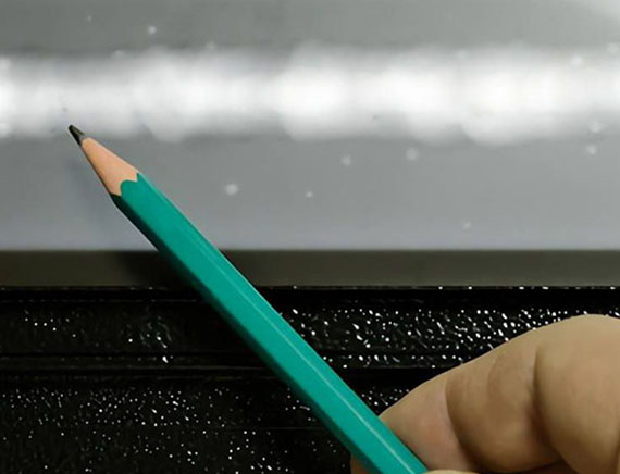
In addition to producing high quality radiographs, the radiographer must also be skilled in radiographic interpretation. Interpretation of radiographs takes place in three basic steps: (1) detection, (2) interpretation, and (3) evaluation. All of these steps make use of the radiographer's visual acuity. Visual acuity is the ability to resolve a spatial pattern in an image. The ability of an individual to detect discontinuities in radiography is also affected by the lighting condition in the place of viewing, and the experience level for recognizing various features in the image.

Review of Radiographic
films

Review of Radiographic
films

Evaluation based on acceptance criteria

Evaluation based on acceptance criteria
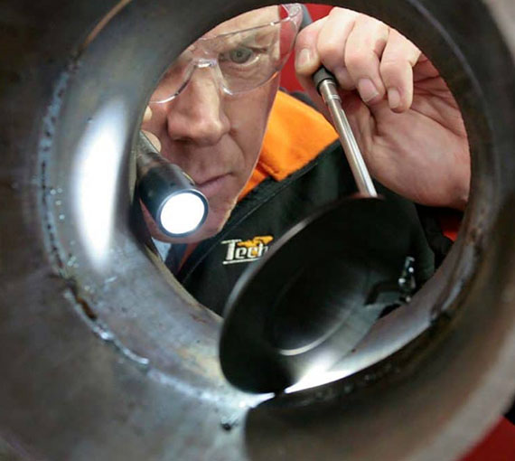
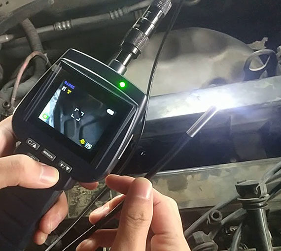
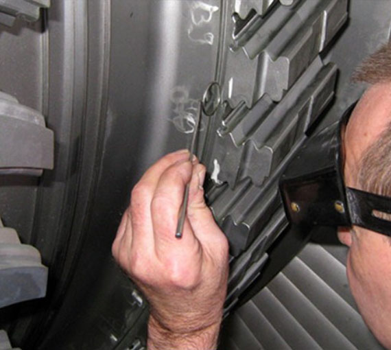
Visual testing (VT) the oldest and most common NDT method, is important in the discipline of non-destructive testing and is widely used on a variety of specimen types. At its core, VT is the observation of a specimen, either directly or indirectly. Observation may be used to locate and size the surface and surface-breaking discontinuities in opaque materials, detect subsurface discontinuities in translucent or transparent materials, detect structural problems, observe or measure clearance, detect leaking, and judge conformance to a specification (for example, a missed operation or improper assembly). Everyone is familiar with the basic principles of direct visual testing, as we regularly apply this technique in our personal lives. For example, we use VT to select the best fruit at the grocery store, with the aid of the additional senses of touch and smell.
(Plate & Pipe Samples):

Finding Surface Visible Indications on Butt Weld Plates (Face & Root)

Finding Surface Visible Indications on Butt Weld Plates (Face & Root)

Finding Surface Visible Indications on Butt Weld Pipes (Face & Root)

Finding Surface Visible Indications on Butt Weld Pipes (Face & Root)